return to
 Bad pictures ? Click here
 Machining the Karl shell using my Sherline lathe and mill
As always when I start a project, the first step is to draw the pieces I want to machine. This give my a idea of the volume, difficulties and most importantly I can adjust the various sizes to match my actual tooling. Drawing any hole size is easy, but to drill it I need a drill bit that match the drawing. And most of the time, adjusting a dimension imply to adjust many others, to keep as close as possible the original proportions.
Here's the typical documents I use for such a project:
Lots of enlarged photographs, plans and hand made drawings.
The typical drawings I make looks like that:
Of course I use my little GridOmatic for the graph paper, it was only written for that purpose in fact, and hopefully now it is useful to others.
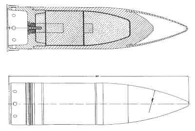
It is obvious on this original drawing of a Karl 60cm long shell that it is made in 3 separate parts. The base, a central body and the aerodynamic cone nose. So the shell will naturally be machined in 3 parts. Why would I simulate a seal where I can have the real thing ?
And now, machining time !
First, the central body of the shell. The end near the nose must be rounded, but for now it's just a plain cylinder.
After machining the details, separation from the cast aluminium rod using the cutting tool. The result is a hollow tube, matching the external details of the original plan .
Then the nose. First, a rough shape is turned according to the staircase cutting planned in the drawing.
The piece is separate, and reversed to be able to drill and thread a hole in its base.
Then back to the original cutting position, and separate from the base.
Using a little fixture to grip the cylinder, and with a bold going through and screwed in the nose, the shell is assembled in the lathe...
... and filed and polished until the perfect curvature is reached. Note that I curved at that time the end of the central body part that was originally a plain cylinder. That's how the seal is so perfect ! I cheated !!
The body and nose are done. To reach the perfect curvature, numerous back and forth from the lathe to the scanner where necessary, to compare the original drawing and a scan of the shell in progress.
Now the base. First, a simple cup is shaped out of a rod.
The cup is then drilled and threaded.
Holes are drilled around... a rule to remember : The drill bit you need is always the one broken the day before.
Small details are added with a end mill. Another rule : No matter how much different end mills you have, you never have the proper one.
And the cup is finally separated from the rod.
Finally, the last part with this particular flower design. A disk of the proper diameter is shaped...
And details are added, using a small end mill, the rotary table, and carefully planned movements. Now I know why I learned trigonometry at school !! This cap disk is then separated from the rod and inserted in the base cup.
The final result. All I need to verify is the conformity of my scaled model with the real thing.
Oh, BTW overall length is 72mm (2"7/8) diameter 17mm (11/16"). At real scale, a mighty length of 251cm (8'3"), diameter 60cm (23"5/8) !
First I compared with the original plan. You can see in the middle my own shell, and in the bottom the aluminium shell supplied with the Dragon kit. See how the nose is way too pointed ? And of course, the base is dead flat, with no details at all, no holes, no flower pattern, nothing.
Then I used a few photographs to compare the real shell and my model, trying to find an almost identical photographic angle... not as easy as it seem !
Quite close, uh ?